


Alizn Professional Customization
SMD Pogo Pins
Spring Loaded SMD Pin Catalog
SMD pogo pin, also known as spring-loaded smd pins, smd spring contacts, or through-hole spring-loaded pins, are primarily used to establish reliable electrical or signal connections between components. They ensure consistent conductivity and stable contact performance in various electronic applications.
SMD Pogo Pins Overview
SMD Pogopin Product Details
With advanced technology and expert craftsmanship, we create durable, high-performance custom smd pogo pin / smd spring connector pin tailored to each project’s needs.
What is a SMD pogo pin
A SMD pogo pin is a spring-loaded electrical contact specifically designed for surface-mount technology (SMT/SMD) assembly on printed circuit boards. Unlike through-hole pogo pins, which require drilled holes, SMD pogo pins feature a flat or castellated base that can be directly soldered onto PCB pads during reflow soldering. This makes them ideal for automated production lines, compact device layouts, and high-volume electronics manufacturing.
Structurally, an SMD pogo pin consists of three core components: a barrel, a plunger, and an internal spring. When external pressure is applied, the plunger compresses into the barrel while maintaining stable contact force through the spring. This design ensures consistent electrical conductivity, compensates for mechanical tolerances, and provides reliable performance even under repeated compression cycles.
How to install SMD pogo pin
To install an SMD pogo pin, first design accurate SMT pads on the PCB according to the pin’s footprint. Ensure proper pad spacing, solder mask opening, and keep-out zones. Place the pogo pins on the PCB using pick-and-place equipment or manual tweezers. During reflow soldering, the pins self-align as solder paste melts, forming stable joints. After reflow, inspect solder joints for tilt, insufficient solder, or misalignment. Avoid excessive mechanical force on the pins before the solder fully cools. Finally, test compression height and electrical continuity to ensure reliable contact in the finished assembly.
SMD pogopin material & parts
SMD pogo pins are compact spring-loaded connectors designed for surface-mount assembly. The plunger (top pin) is typically made of brass or beryllium copper, then plated with nickel and gold to improve conductivity and wear resistance. The barrel (outer tube) is usually brass with hard gold plating for corrosion protection. Inside the barrel, a stainless-steel or music-wire spring provides consistent contact force during compression. The base or SMD pad structure allows reliable soldering onto the PCB. Together, these components enable stable electrical connection under repeated cycles, vibration, and alignment tolerances.
SMD pogopin Internal Structures
There are three commonly used internal structures of Alizn dip pogo pins, namely Plunger bevel structure, Plunger bevel + steel ball structure and Plunger inner hole bevel structure.
The function of the italic structure design is to ensure that when the pogo pins are working, the lateral force created by the interaction between the bevel and the spring keeps the plunger in stable contact with the inner wall of the needle tube. This directs the current primarily through the gold-plated plunger and body, resulting in extremely low contact resistance and maintaining a stable, reliable connection even under frequent mating and unmating.
How do SMD Pogo Pins Work
SMD pogo pins operate based on contact force and contact resistance, which are critical for ensuring stable and reliable connections. There is a direct correlation between contact force and contact resistance: increasing the contact force effectively reduces the contact resistance.
Therefore, maintaining consistent contact force and low contact resistance is essential for a dependable connection. When the bevel and spring mechanism engages, the lateral force is converted into contact force, enabling the gold-plated pin to maintain firm contact with the inner wall of the socket. This results in stable, extremely low contact resistance, ensuring a reliable and consistent connection.
SMD Pogo Pin Contact Resistance
This chart illustrates that during the full compression and release stroke of the SMD pogo pin, the spring force increases smoothly while the contact resistance remains extremely low and stable. This demonstrates a well-engineered internal structure, precise machining tolerances, and high-quality vacuum blind-hole plating that together ensure reliable electrical connectivity and long-term performance stability.
types of spring loaded SMD pin
Selection Guide of SMD Pogo Pin
Select smd pogo pins based on travel length, spring force, contact material, and plating to achieve optimal performance, reliability, and durability.
Fully customizable to meet any electrical, mechanical, or environmental requirements.
| SN | Product Image | Full Stroke (mm) | Initial Height (mm) | Working Height (mm) | Catalog Download |
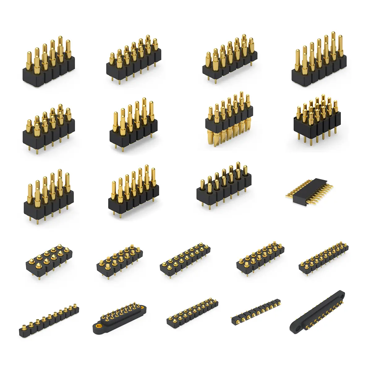
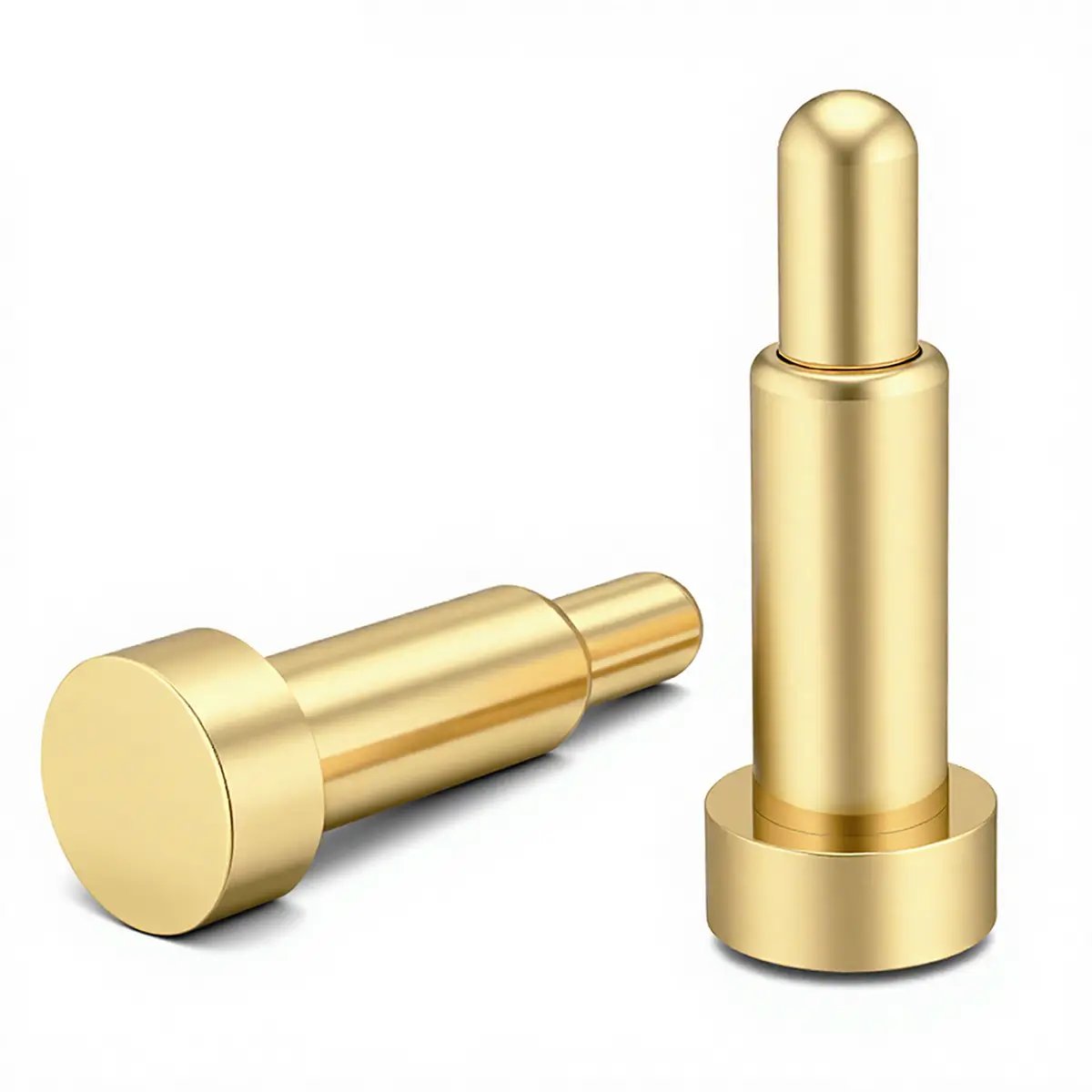
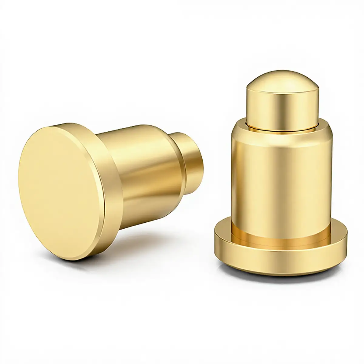
|---|---|---|---|---|---|
| 1 | ![]() |
0.4~0.8 | 1.80~3.00 | 1.40~2.60 | Short Dip Pogo Pins |
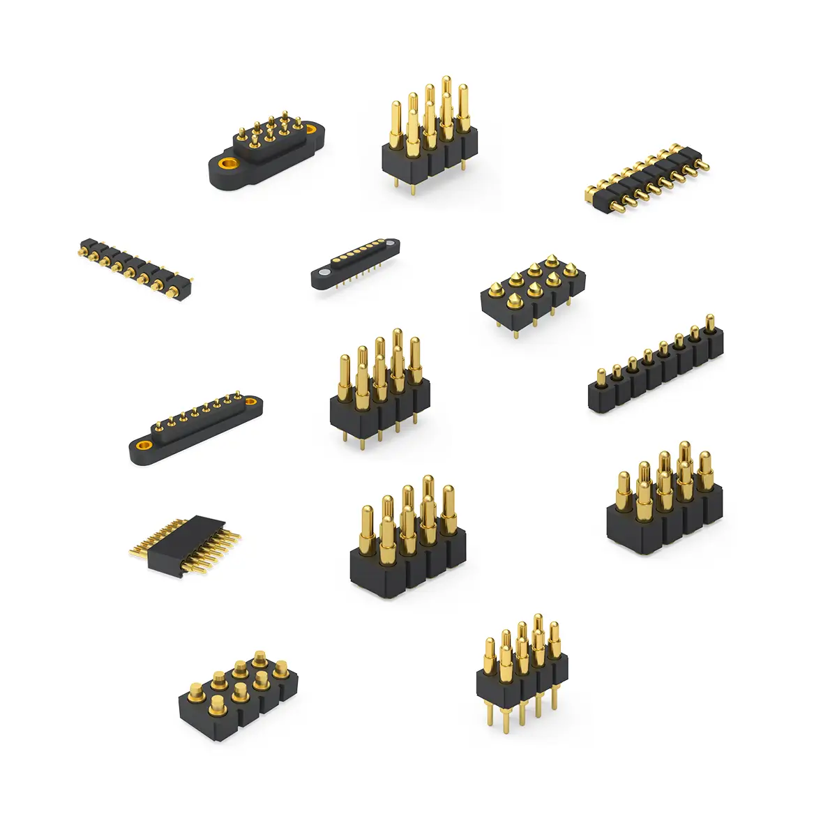
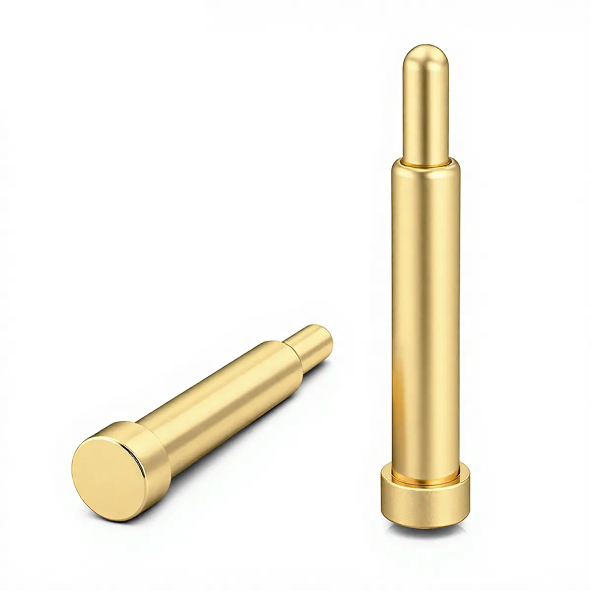
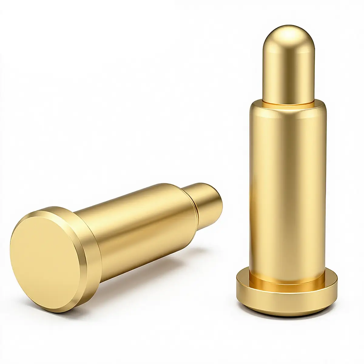
| 2 | ![]() |
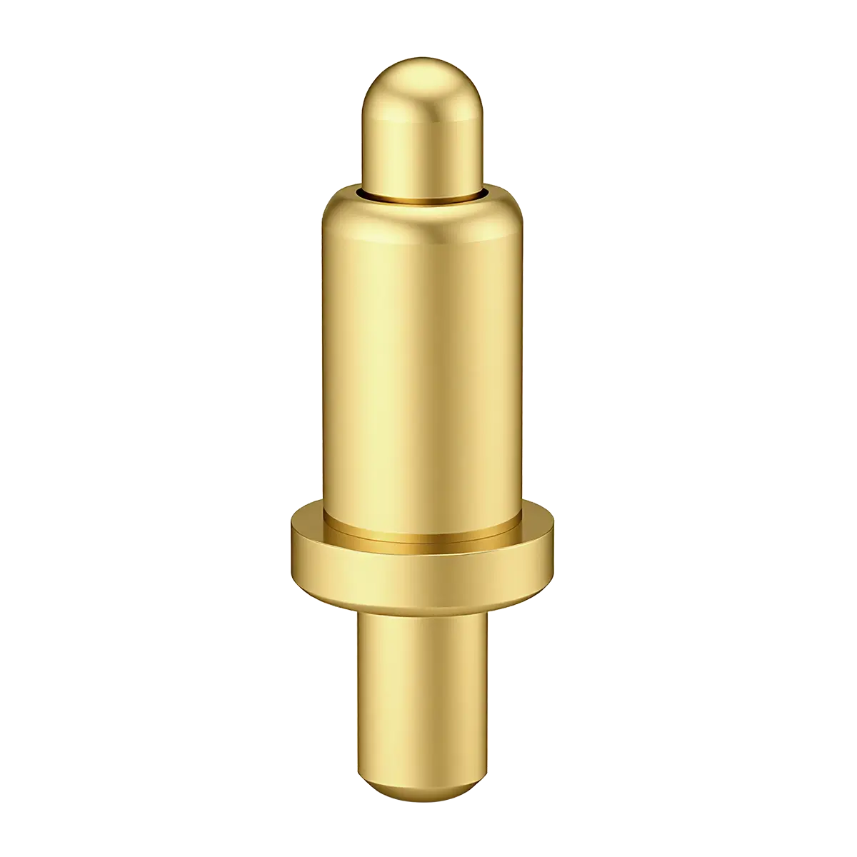
1.00 | 3.15~6.30 | 1.50~5.60 | 1.00 Dip Pogo Pins |
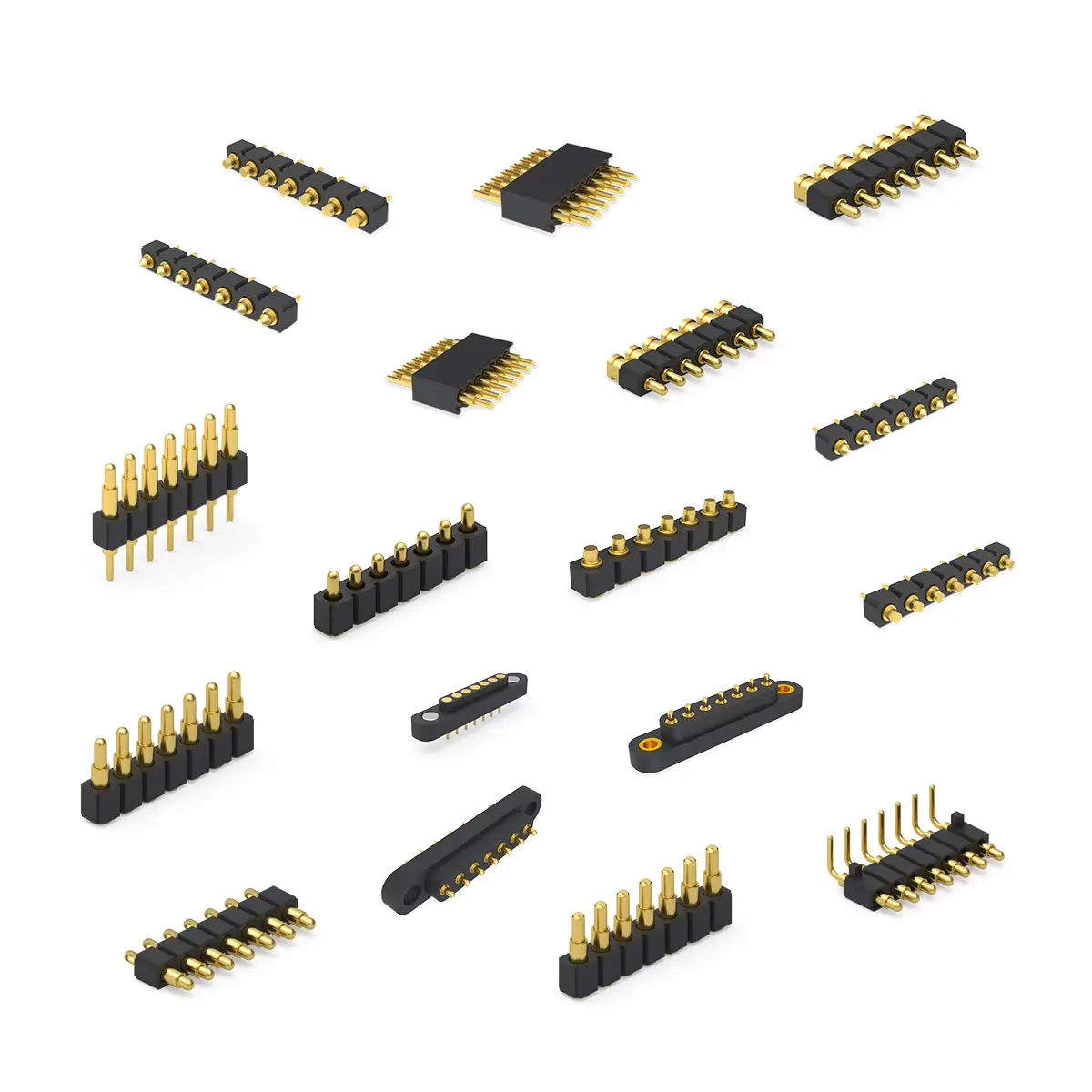
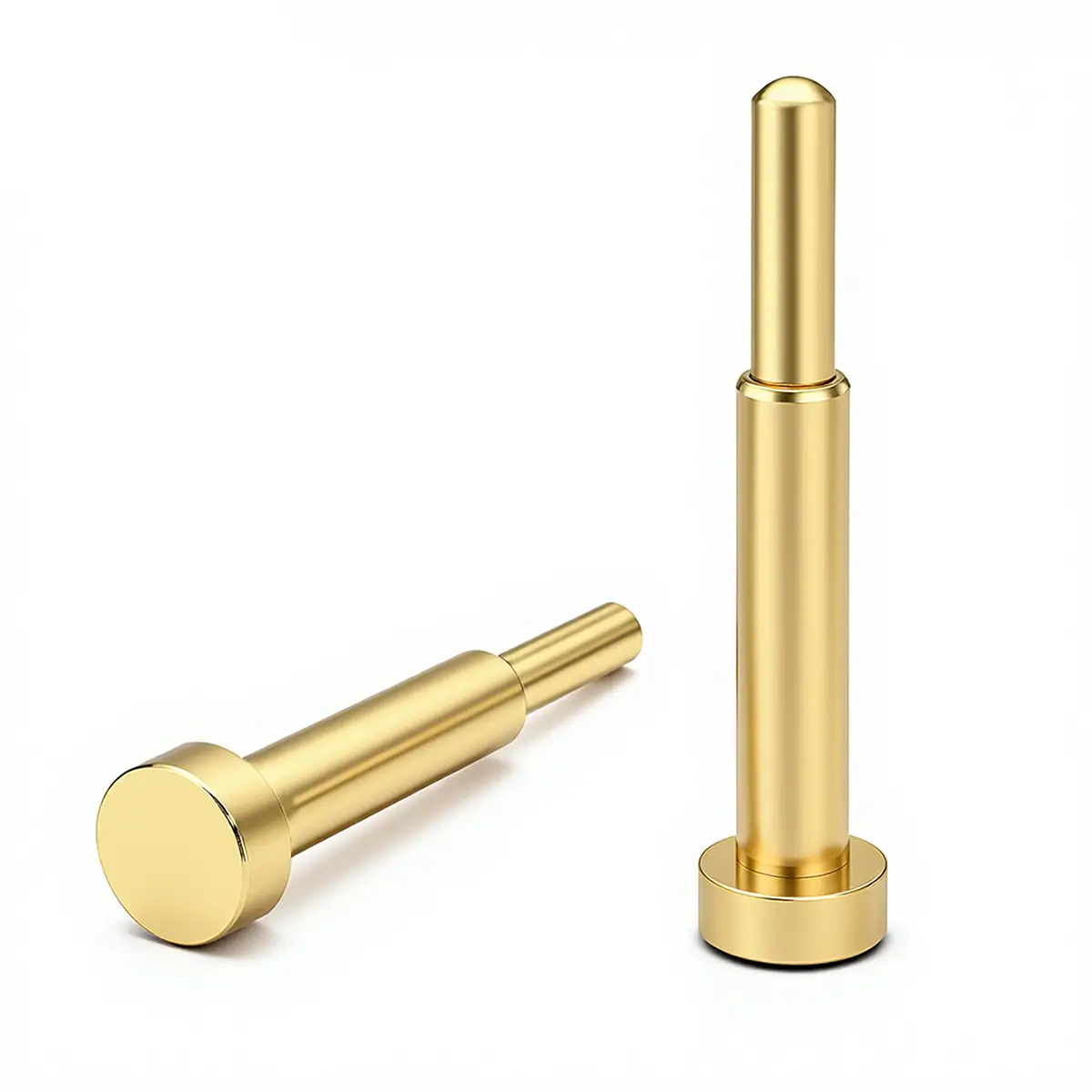
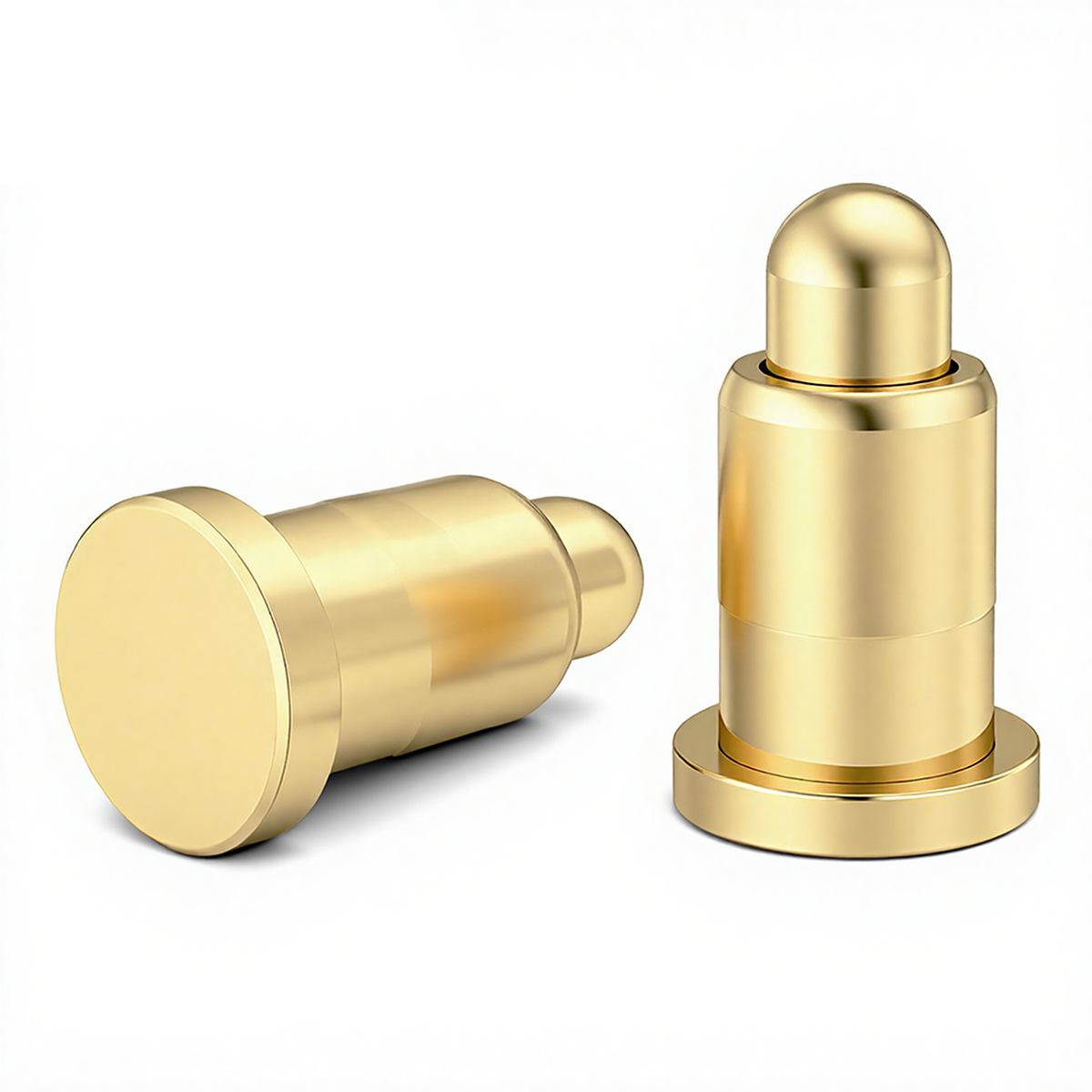
| 3 | ![]() |
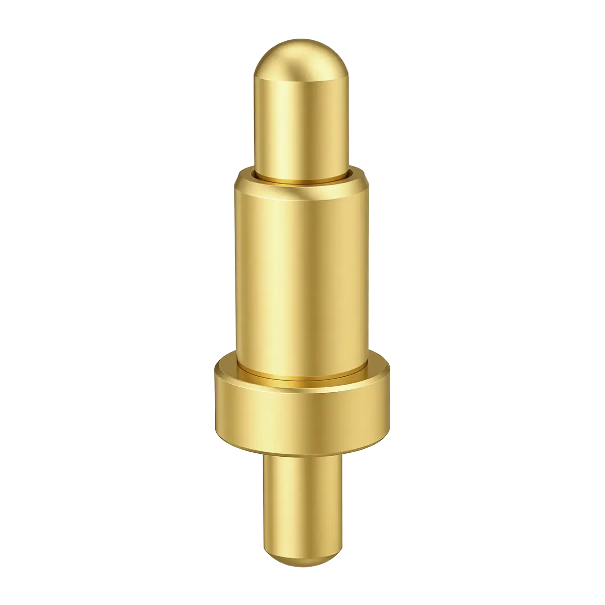
1.50 | 4.50~10.00 | 3.20~9.00 | 1.50 Dip Pogo Pins |
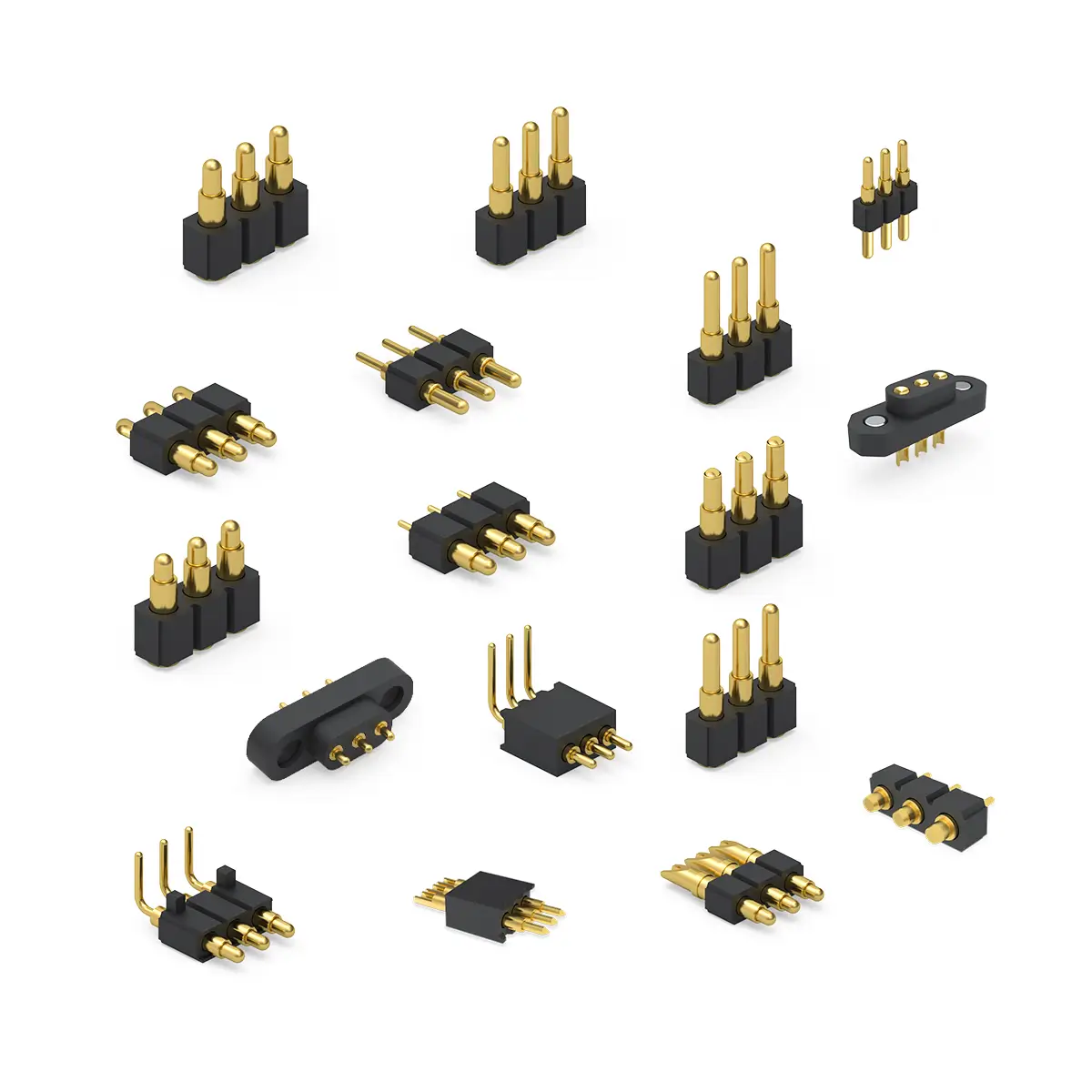
| 4 | ![]() |
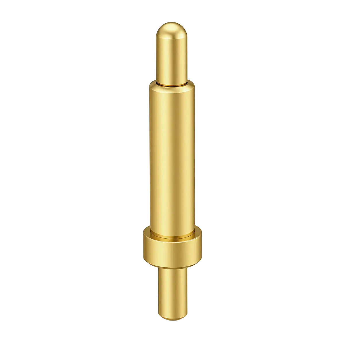
2.00 | 5.80~16.00 | 4.00~15.00 | 2.00 Dip Pogo Pins |
| 5 | ![]() |
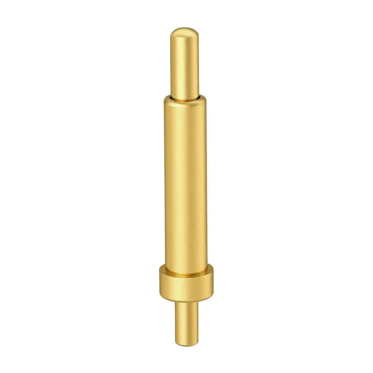
2.50 | 7.10~16.00 | 4.80~15.00 | 2.50 Dip Pogo Pins |
| 6 | ![]() |
3.00 | 8.40~20.00 | 5.60~19.00 | 3.00 Dip Pogo Pins |
| 7 | ![]() |
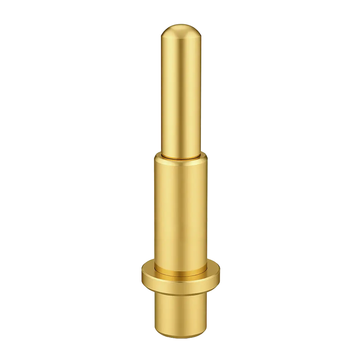
3.50~5.00 | 9.70~20.00 | 6.40~19.00 | 5.00 Dip Pogo Pins |
SMD Spring Loaded Pin Performance
SMD Pogo Pin Technical Parameters
Alizn custom pogo pins are carefully crafted using only the finest materials.
Our production team offers superior craftsmanship with over 10 years of experience working with custom smd pogo pins / smd pogo pin connectors.
| Items | Details |
|---|---|
| Material | Plunger: Lead-Free Copper Alloy |
| Body: Lead-Free Copper Alloy | |
| Spring: Stainless Steel | |
| Solid Pin: Lead-Free Copper Alloy | |
| Main Technical Parameters | Standard state: |
| Operating temperature: -40~+120°C (Standard) | |
| Operating humidity: 20-85% RH | |
| Storage temperature: -10~+50°C | |
| Storage humidity: 20-85% RH | |
| Rating voltage: 36V AC/DC (Standard) | |
| Rating current: 2A/Pin Continuous (Standard) | |
| Contact resistance: 30 mΩ Max. (Standard) | |
| Withstanding voltage: 250V AC, 1 Minute | |
| Insulation resistance: 500 MΩ Min. | |
| Durability: 10,000 Cycles (Standard) | |
| Working Spring Force: 40~120 gf (Standard) | |
| Electroplating | Plunger: Ni Plating 1.4μm, Gold Plating 0.30μm |
| Body: Ni Plating 1.4μm, Gold Plating 0.10μm | |
| Solid Pin: Ni Plating 1.4μm, Gold Plating 0.10μm | |
| Contact Type | Vertical Contact Type |
| Installation Method | SMT automatic placement machine + Reflow soldering |
| Plugin machine + Wave soldering | |
| Environmental Protection Standard | Comply with EU RoHS and Alizn standards |
Upload Your CAD File
To begin, provide your contact details and upload the CAD file or detailed product requirements of your design. This allows us to create a detailed 3D model of the part or prototype you're looking to produce.
Receive a Quote & Design Review
Within 12 hours, we’ll send you a detailed quote along with Design for Manufacturability (DFM) feedback. This ensures the feasibility of your project and gives you a clear idea of the costs involved.
Confirm Your Order & Begin Production
Once you approve the quote and design, we’ll proceed with the production of your custom smd pogo pins.
Shipping & Delivery
Your project enters our manufacturing queue the morning after we receive your approval. On average, custom orders ship within 10-15 business days. In-stock products and samples ship within 48 hours.
Just 4 Steps
Custom SMD Pogo Pin Quotation Process
From detailed consultation to final delivery, we make custom pogo pin orders simple and easy. We pride ourselves on providing exceptional customer service by anticipating your needs, offering customized solutions and on-time delivery.
SMD Spring Loaded Pins Electroplating
SMD Pogo Pin Surface Treatment
Various surface treatment methods to meet your needs
Electroplated Gold-Golden Yellow
Electroplated Nickel—Silver White
Before Electroplating - Brass Color
Packaging Options for SMD Pogopin
Pogo Pin Packaging Method
Enabling you to move seamlessly from receiving to production without compromise.
Pogo Pins Vacuum Carrier Tape Packaging
Pogo Pin Connector Vacuum Carrier Tape Packaging
SMD Contact Pin Customization Process
From Design to Quality Control
Every Step Tailored to Perfection
Alizn smd pogo pin customization process ensures precision, quality, and efficiency at every stage. From innovative design and advanced production to rigorous quality control, we transform your ideas into high-performance solutions. Serving diverse industries, we specialize in creating prototypes and full-scale production, turning your vision into reality with unmatched expertise and attention to detail.
- RX Feugiat 2000
- 4-5 months
- $ 8,400
Professional Equipment For SMD Springloaded Pin
The Equipment Behind Custom Pogo Pins
Our professional equipment provides complete solutions for pogo pin customization, ensuring high precision, efficiency, and cost-effectiveness.
From design to production, we meet strict quality standards, addressing complex shapes and performance needs.
automatic lathe
High-speed auto-feeding turning
milling machine
Complex precision machining
stamping press
High accuracy & rigidity
spring coiling machine
Free-height & wire-diameter precision
electroplating machine
Uniform, clean
coordinate measuring machine
Dimensional & tolerance verification
Alizn Pogo Pin
Related Pogo Pin
From initial prototypes to large-scale production, we ensure top-quality results and help you achieve your manufacturing goals.
SMD Pogo Pin FAQ
Alizn high-performance pogo pins, ideal for functional tests or end-use applications. Explore our FAQs to discover more about our pogo pin solutions and related technical support.
We need drawings or key specs: size, stroke, force, current, plating, and usage.
Standard parts: 3–7 days. Custom parts: 2–4 weeks depending on complexity.
Yes, sample testing can be provided before mass production.
Yes, we can design sealed / IP67–IP68 waterproof structures.
Yes, we support full customization based on size, force, plating, and structure.


