Multi Pin Connector

Alizn Professional Customization

Multi Pogo Pin Connector
Multi Pin Spring Loaded Connector Catalog

Multi pin connector, also known as multi pin electrical connectors or multi pin spring loaded connector, are primarily used to create stable and reliable electrical or signal pathways between two components. They provide secure mating, consistent conductivity, and dependable performance across a wide range of electronic and power transmission applications.

Multi Point Pogo Pins Connector Overview

Multi Pin Pogo Connector Product Details

With advanced technology and expert craftsmanship, we create durable, high performance custom pogo pin connector tailored to each project’s needs. 

What is multi point pogo pin connector

Multi point pogo pin connectors are compact, spring loaded electrical contacts designed for reliable connections in various electronic devices. They consist of a barrel, plunger, and internal spring, enabling consistent contact pressure. These connectors are highly durable, often enduring hundreds of thousands of mating cycles, making them ideal for applications requiring frequent connection and disconnection. Multi pin configurations, typically ranging from 10 to 20 pins, are achieved by grouping individual pogo pins densely within a fixture or insulator carrier, simplifying complex circuit designs and ensuring stable electrical pathways for power and data transmission.

How to install multi point pogo pins connector

Installing multi point pogo pin connectors involves various mounting technologies to suit diverse application needs. Common methods include surface mount technology for direct board placement, through hole technology for robust connections, wire mount for cable integration, and free hanging configurations. Pins can be secured via press fit, swaged, crimped, soldered, or solderless techniques. For multi pin arrays, precise alignment is crucial, often achieved using insulator carriers or specialized fixtures. Specific designs like solder cups facilitate cable attachment, while right angle and vertical configurations accommodate different board layouts, ensuring optimal performance and long term reliability across multiple industries.

Multi pin pogo connector material & parts

Multi pin pogo connectors are engineered from specific materials to ensure optimal performance and longevity. The primary components include a plunger, barrel, and an internal coil spring. Barrels and plungers are typically crafted from high conductivity brass or copper alloys, such as C3604 brass. To enhance electrical conductivity and corrosion resistance, these components often feature a base coating of nickel, followed by a top plating of gold or palladium. The internal springs are commonly made from durable materials like stainless steel or music wire, providing consistent force and reliable mechanical action throughout the connector’s operational lifespan in challenging environments.

dip pogo pins internal structures

Multi pin spring loaded connector Internal structures

The internal structure of a multi pin spring loaded connector is fundamentally composed of three key parts: the plunger, the barrel, and the spring. The plunger, which makes contact with the mating surface, moves within the barrel. The spring, housed within the barrel, provides the necessary force to maintain constant contact. Advanced designs may incorporate features like ball point plungers for improved contact stability or back drill designs to optimize spring travel. For multi pin arrays, an insulator carrier or plastic housing integrates these individual pins into a cohesive unit, ensuring precise spacing and electrical isolation between each contact point.

How multi pin spring connector Work

Multi pin spring connectors operate on a simple yet effective mechanical principle. When the connector mates with a target surface, the plunger of each individual pogo pin is pressed inward, compressing its internal spring. This compression generates a consistent and controlled spring force that pushes the plunger tip against the mating pad. This continuous pressure ensures a stable and low resistance electrical connection, even in dynamic environments subject to vibration or shock. The spring’s resilience allows for repeated compression and extension, maintaining reliable contact over numerous mating cycles, which is crucial for high durability applications and frequent device interactions.

Multi pin pogo connectors contact resistance

Contact resistance is a critical performance parameter for multi pin pogo connectors, typically ranging from less than 20mΩ to 50mΩ at mid stroke. This low resistance is vital for efficient power and signal transmission. Several factors influence contact resistance, including the plating material, spring force, and contact geometry. Gold plating significantly reduces resistance and enhances corrosion resistance, especially in harsh environments, ensuring stable performance over extended periods. Higher spring forces generally lead to lower contact resistance by increasing the contact pressure. Measurements are usually taken at the contact terminals to confirm the connector’s electrical integrity and long term reliability.

types of multi point pogo pin connectors

Selection Guide of Multi Point Spring Loaded Connectors

Select spring pin connector based on travel length, spring force, contact material, and plating to achieve optimal performance, reliability, and durability.
Fully customizable to meet any electrical, mechanical, or environmental requirements.

Connector Type Product Image Full Stroke (mm) Initial Height (mm) Working Height (mm) Detailed Selection
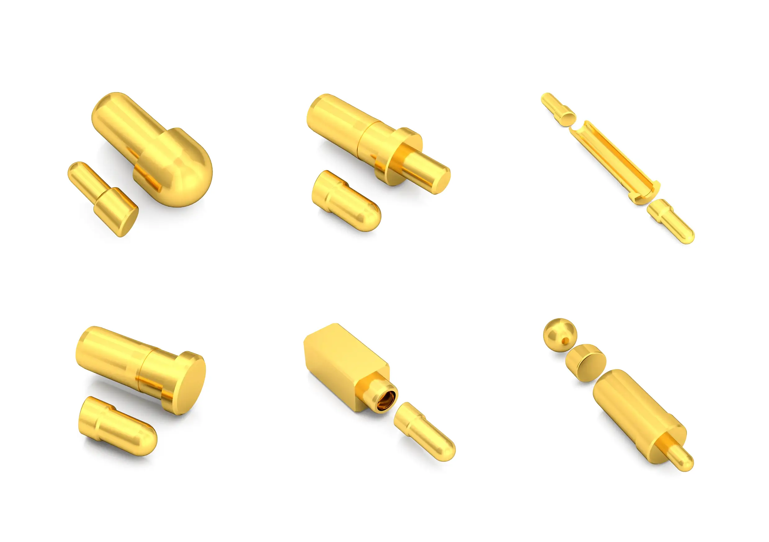
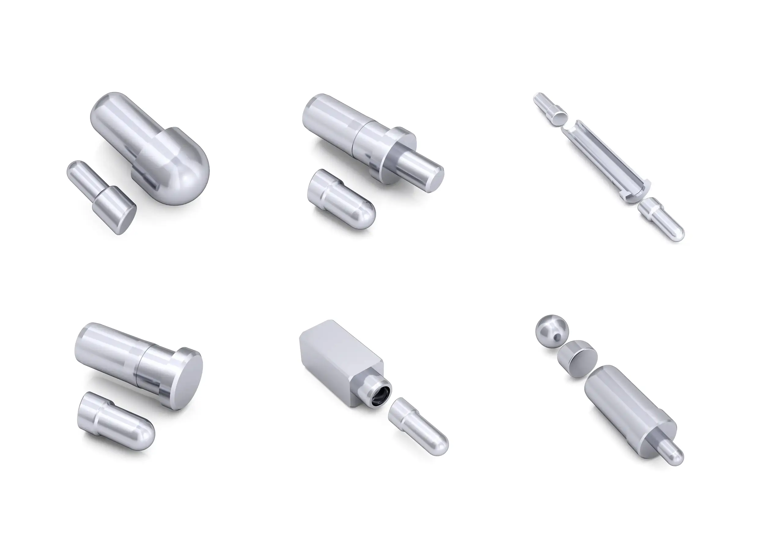
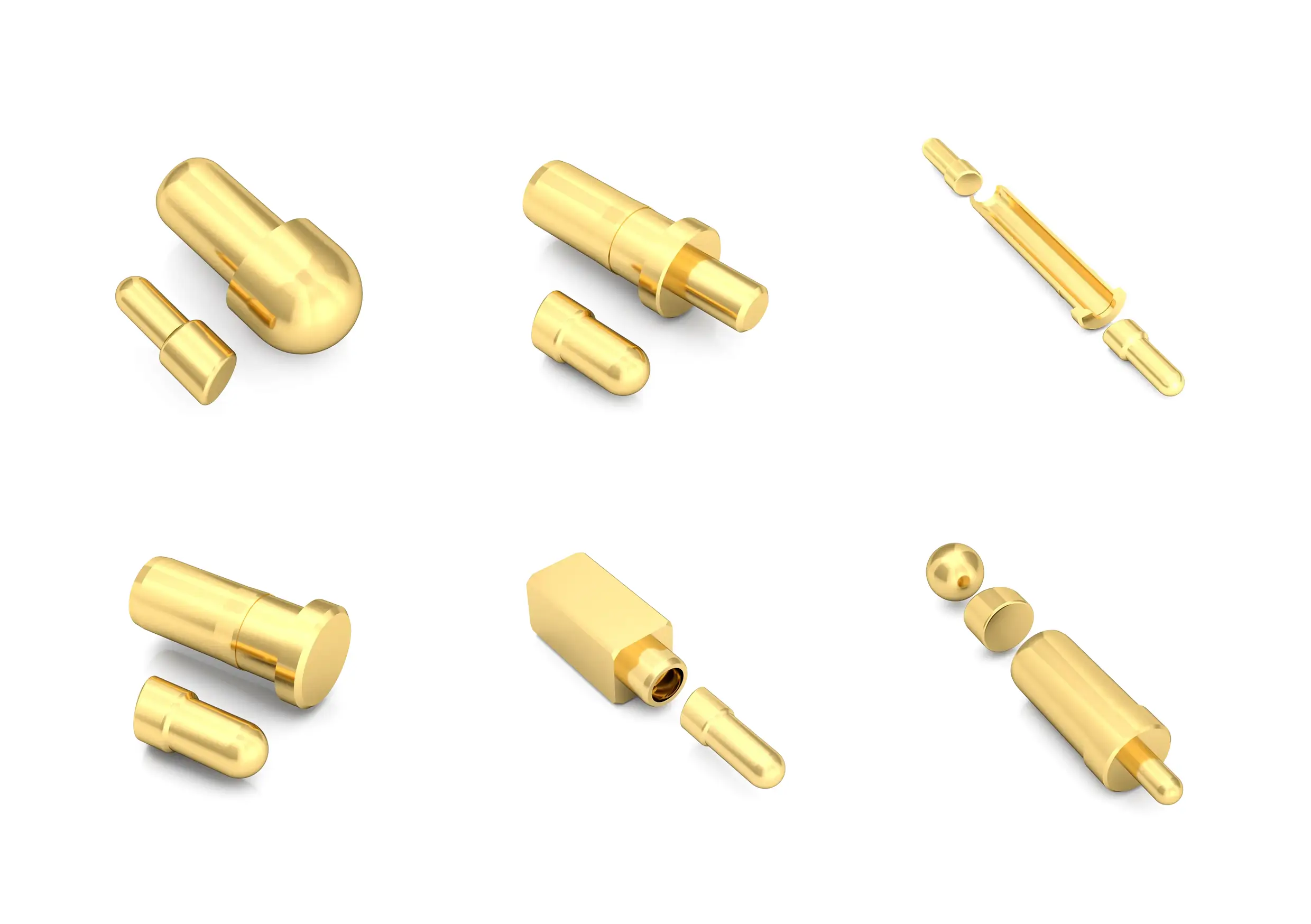
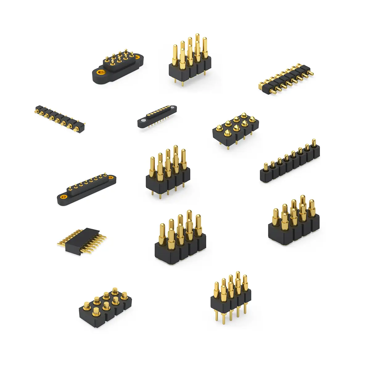
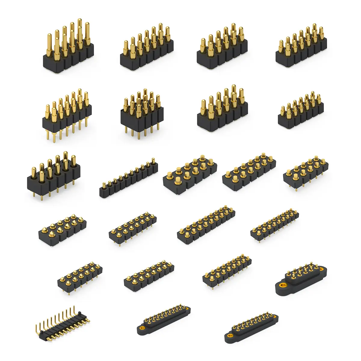
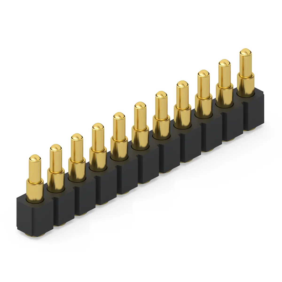
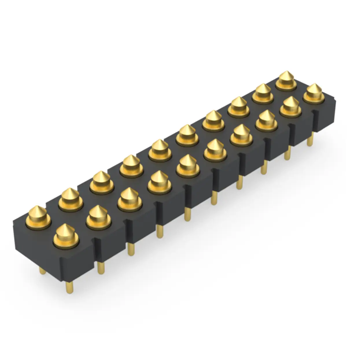
Dip
Pogo Pin Connector
0.4~5.0 1.80~20.0 1.40~19.0 dip pogo pin
detailed selection
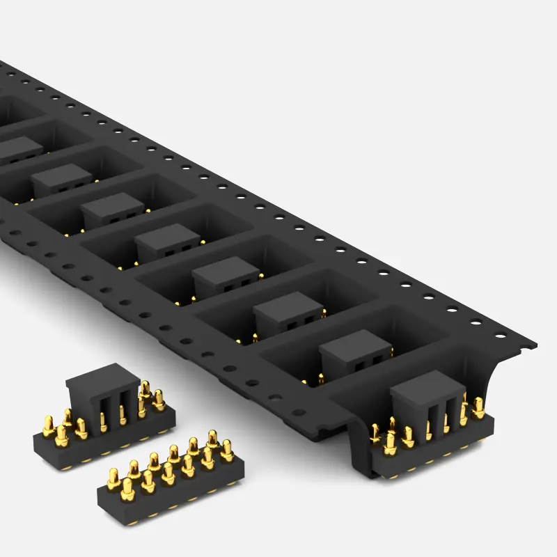
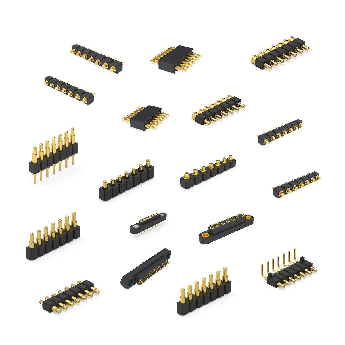
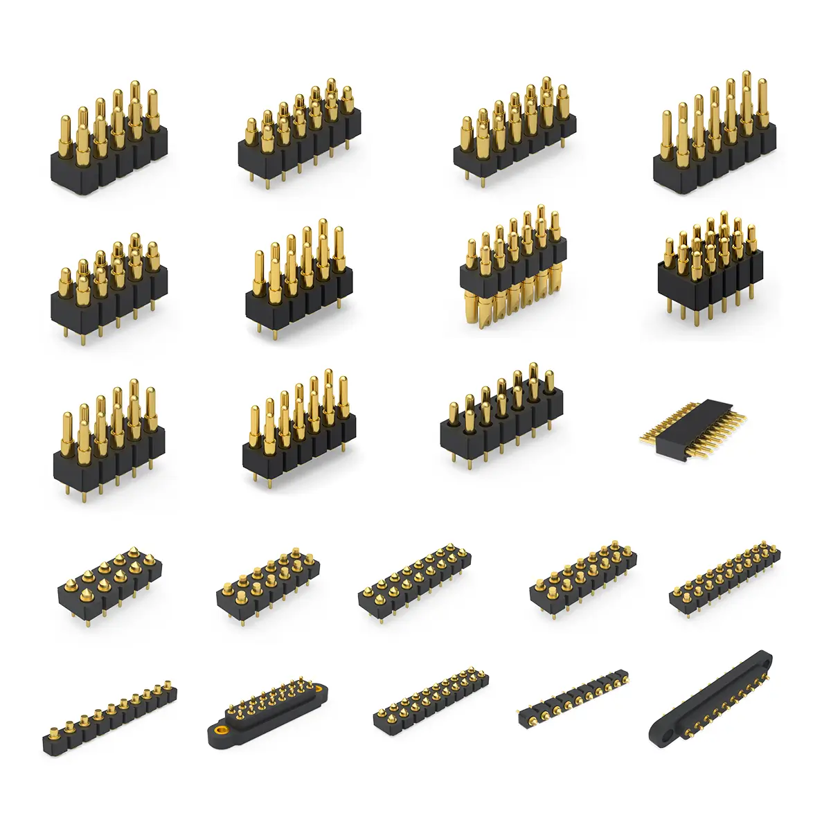
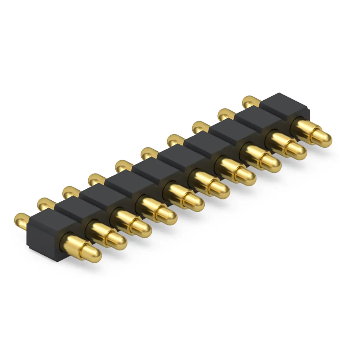
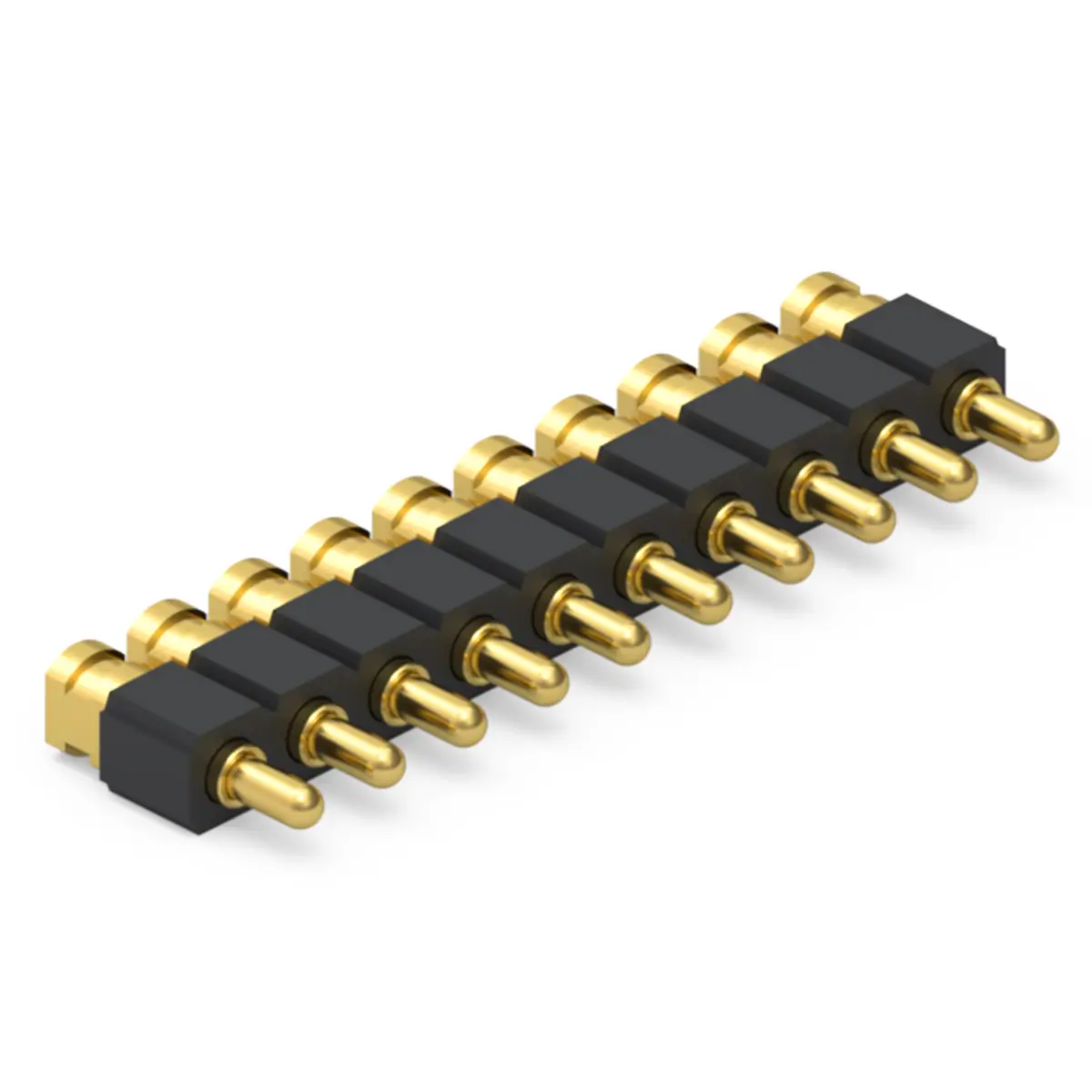
SMD
Pogo Pin Connector
0.4~3.0 1.80~20.0 1.40~19.0 smd pogo pin
detailed selection
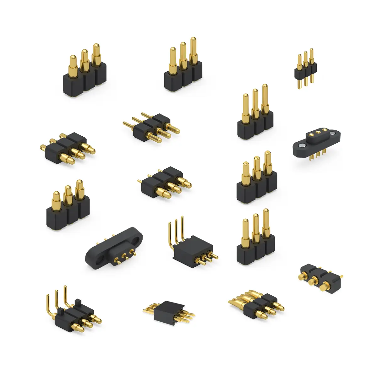
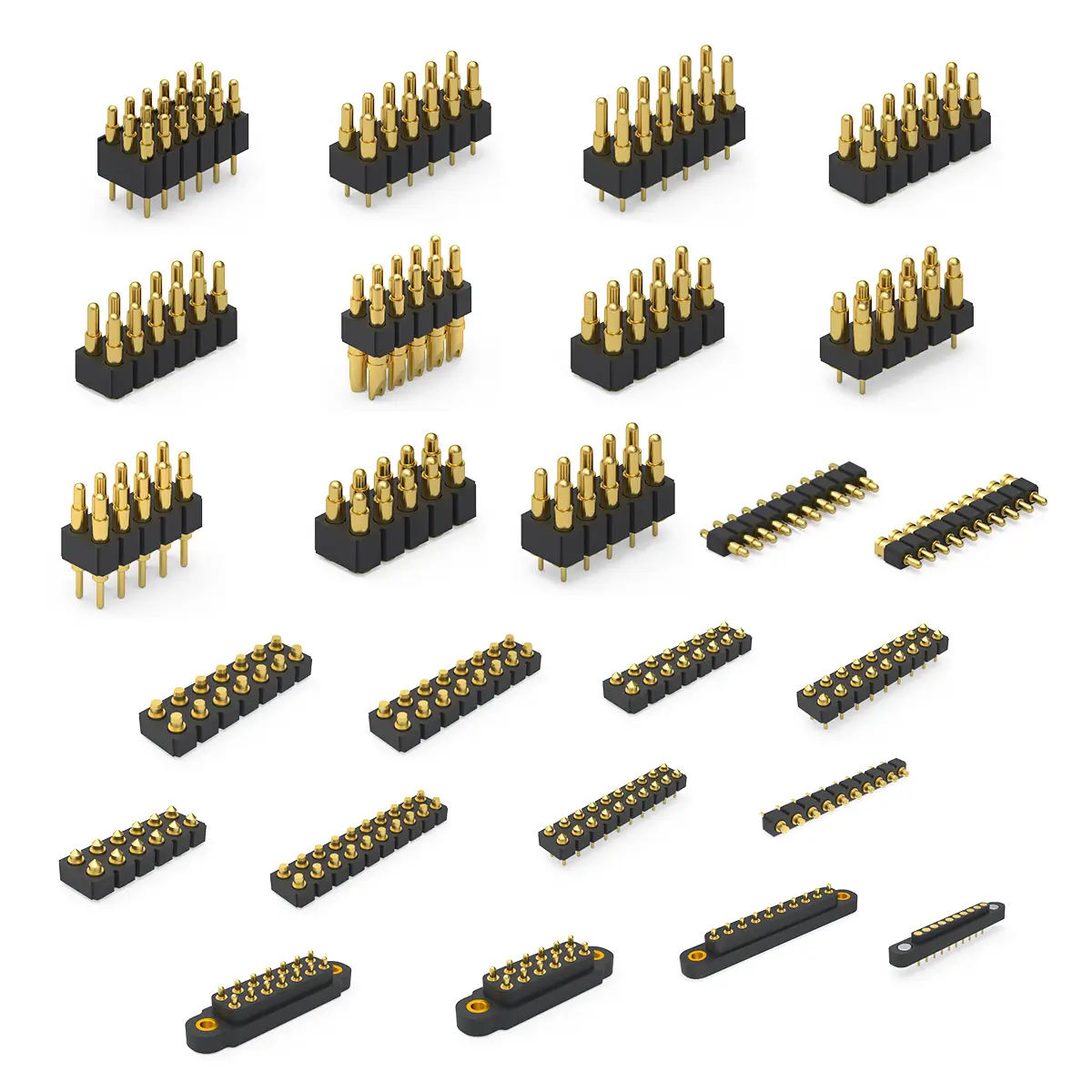
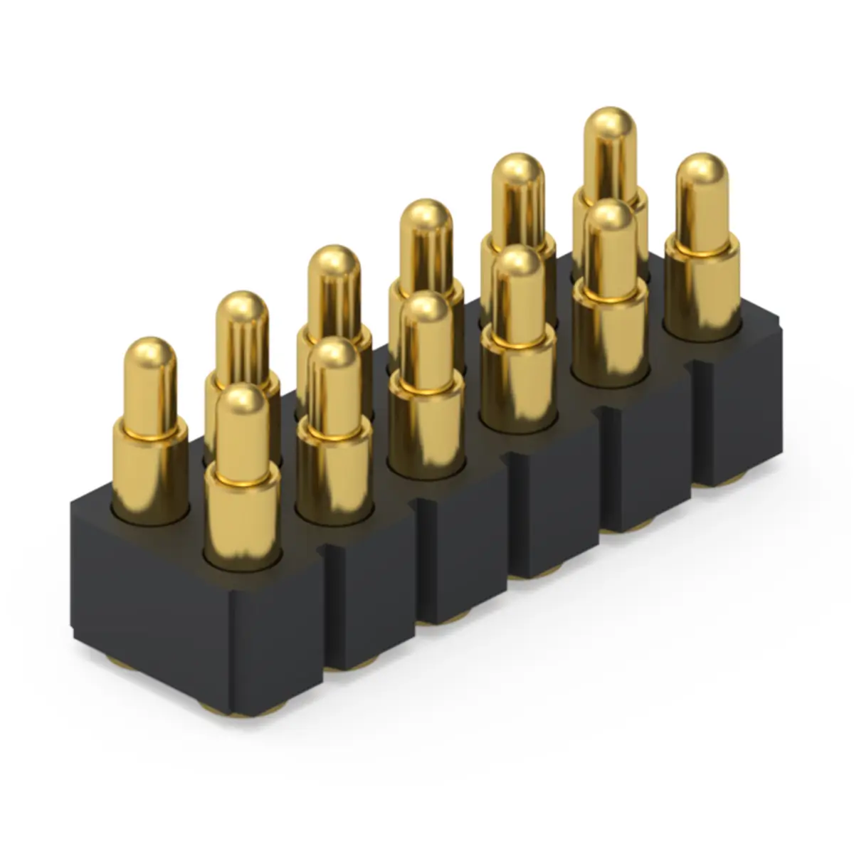
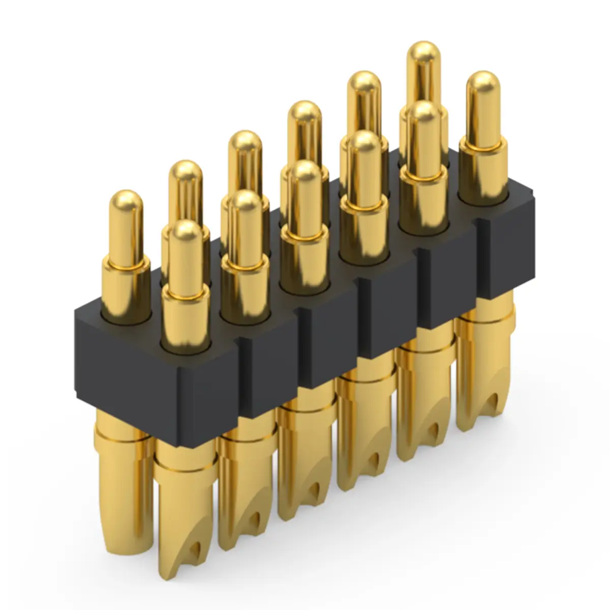
Double Ended
Pogo Pin Connector
1.0 – 4.0 10.0 – 35.0 7.0 – 30.0 double ended pogo pin
detailed selection
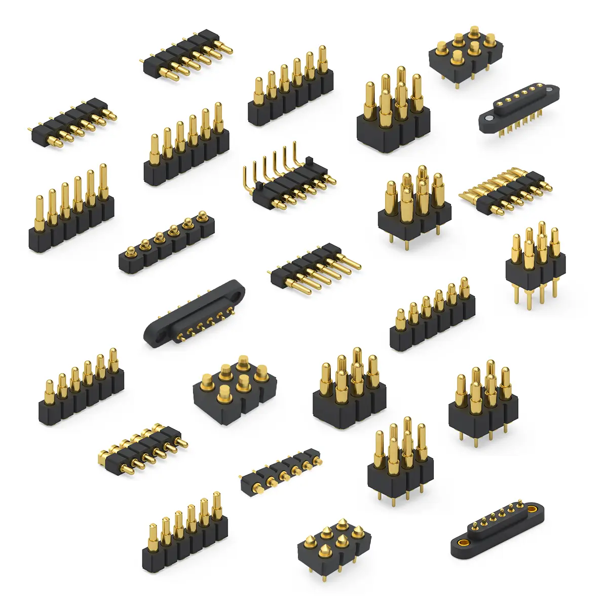
Right Angle
Pogo Pin Connector
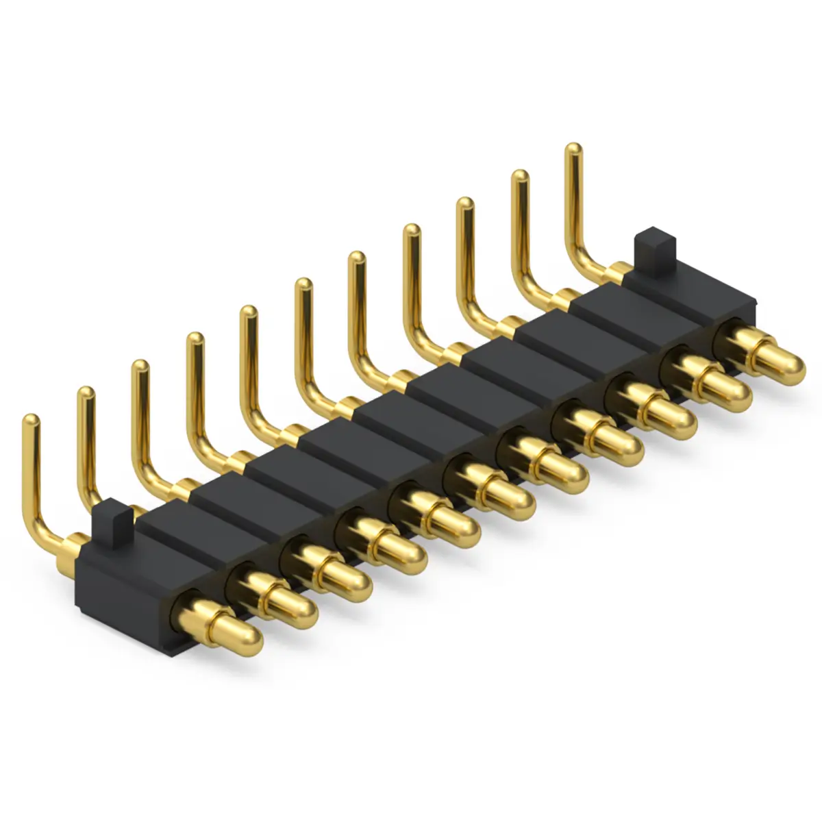
0.8 – 3.0 6.0 – 16.0 4.5 – 14.0 right angle pogo pin
detailed selection
Rolling
Pogo Pin Connector
0.4 – 2.2 4.5 – 13.0 3.8 – 11.5 rolling pogo pin
detailed selection
Side Contact
Pogo Pin Connector
0.5 – 2.2 5.5 – 15.0 4.8 – 13.5 side contact pogo pin
detailed selection
Solder Cup
Pogo Pin Connector
1.0 – 3.5 8.0 – 20.0 6.0 – 17.0 solder cup pogo pin
detailed selection
High Current
Pogo Pin Connector
0.8 – 3.5 6.0 – 18.0 4.8 – 15.0 high current pogo pin
detailed selection
Pancil
Pogo Pin Connector
0.4 – 3.0 3.5 – 13.0 3.0 – 11.5 pancil pogo pin
detailed selection
Multi Point Pogo Pin Connector Performance

Multi Pin Connector Technical Parameters

Alizn custom pogo pins connector are carefully crafted using only the finest materials.
Our production team offers superior craftsmanship with over 10 years of experience working with custom spring loaded connector.

Items Details
Material Plunger: Lead-Free Copper Alloy
Body: Lead-Free Copper Alloy
Spring: Stainless Steel
Solid Pin: Lead-Free Copper Alloy
Main Technical Parameters Standard state:
Operating temperature: -40~+120°C (Standard)
Operating humidity: 20-85% RH
Storage temperature: -10~+50°C
Storage humidity: 20-85% RH
Rating voltage: 36V AC/DC (Standard)
Rating current: 2A/Pin Continuous (Standard)
Contact resistance: 30 mΩ Max. (Standard)
Withstanding voltage: 250V AC, 1 Minute
Insulation resistance: 500 MΩ Min.
Durability: 10,000 Cycles (Standard)
Working Spring Force: 40~120 gf (Standard)
Electroplating Plunger: Ni Plating 1.4μm, Gold Plating 0.30μm
Body: Ni Plating 1.4μm, Gold Plating 0.10μm
Solid Pin: Ni Plating 1.4μm, Gold Plating 0.10μm
Contact Type Vertical Contact Type
Installation Method SMT automatic placement machine + Reflow soldering
Plugin machine + Wave soldering
Environmental Protection Standard Comply with EU RoHS and Alizn standards

Upload Your CAD File

To begin, provide your contact details and upload the CAD file or detailed product requirements of your design. This allows us to create a detailed 3D model of the part or prototype you're looking to produce.

Receive a Quote & Design Review

Within 12 hours, we’ll send you a detailed quote along with Design for Manufacturability (DFM) feedback. This ensures the feasibility of your project and gives you a clear idea of the costs involved.

Confirm Your Order & Begin Production

Once you approve the quote and design, we’ll proceed with the production of your custom pogo connector.

Shipping & Delivery

Your project enters our manufacturing queue the morning after we receive your approval. On average, custom orders ship within 10-15 business days. In-stock products and samples ship within 48 hours.

Just 4 Steps
Custom Multi Point Spring Connector Quotation Process

From detailed consultation to final delivery, we make custom pogo pin connectors order simple and easy. We pride ourselves on providing exceptional customer service by anticipating your needs, offering customized solutions and on time delivery.
Multi Point Spring Loaded Connectors Electroplating

Multi Point Spring Pin Connector Surface Treatment

Various surface treatment methods to meet your needs

Electroplated Gold - Golden Yellow
Electroplated Nickel - Silver White
Before Electroplating - Brass Color
Packaging Options for Multi Pin Connector

Multi Point Pogo Pin Connector Packaging Method

We ensure each unit is protected from plunger damage, plating scrape, or contamination during transit and storage.
Enabling you to move seamlessly from receiving to production without compromise.
Pogo Pins Vacuum Carrier Tape Packaging
Pogo Pin Connector Vacuum Carrier Tape Packaging
Multi Point Pogo Pins Connector Customization Process

From Design to Quality Control
Every Step Tailored to Perfection

Alizn pogo connector customization process ensures precision, quality, and efficiency at every stage. From innovative design and advanced production to rigorous quality control, we transform your ideas into high performance solutions. Serving diverse industries, we specialize in creating prototypes and full scale production, turning your vision into reality with unmatched expertise and attention to detail.

Professional Equipment For Multi Point Spring Loaded Connector

The Equipment Behind Custom Multi Point Spring Connector

Our professional equipment provides complete solutions for pogo connectors customization, ensuring high precision, efficiency, and cost effectiveness.
From design to production, we meet strict quality standards, addressing complex shapes and performance needs.

automatic lathe

High speed auto feeding turning

milling machine

Complex precision machining

stamping press

High accuracy & rigidity

spring coiling machine

Free height & wire diameter precision

electroplating machine

Uniform, clean

coordinate measuring machine

Dimensional & tolerance verification

Alizn Spring Loaded Connectors

Related Pogo Pin Connectors

From initial prototypes to large scale production, we ensure top quality results and help you achieve your manufacturing goals.

Pogo Pin Connector Professional Guide

Pogo Pin Connector Knowledge

Alizn explores with you every factor that influences your choice design, functionality, durability, price factors, process, customization options

Multi Point Pogo Pins Connector FAQ

Alizn high performance spring loaded connectors, ideal for functional tests or end use applications. Explore our FAQs to discover more about our spring connector solutions and related technical support.

We need drawings or key specs: size, stroke, force, current, plating, and usage.

Standard parts: 3–7 days. Custom parts: 2–4 weeks depending on complexity.

Yes, sample testing can be provided before mass production.

Yes, we can design sealed / IP67–IP68 waterproof structures.

Yes, we support full customization based on size, force, plating, and structure.